

Building the Bridi “Corben Baby Ace”
Early in the year, Jim Simo gifted to me this Bridi “Corben Baby Ace” kit on the condition that I build it and fly it.
Wow! I can do that!
Then he and Ralph Cunningham came up with a 38cc Zenoah 2-stroke engine for it. (I still owe ’em fifty bucks for that!) and an 18×6 propeller!

All I gotta do is build it…

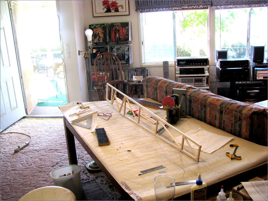
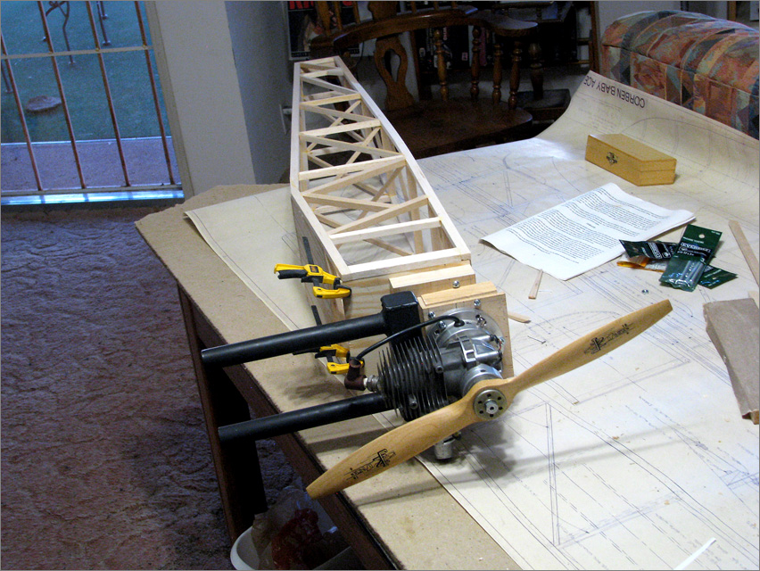
Yikes! This is a big model!

As you can see, I decided to build it in my living room!
This kit is special… the lid on the box is signed by Joseph Bridi, himself!

Doing a bit of research, I see that there are plenty of examples of the full-scale aircraft in action!


Is that WAYNE FLYING THAT AIRCRAFT??


LOTS to do before I can fly mine!

This is a Craftsmans Kit… not for the feint of heart!
The “instruction manual” is four sheets of typewritten notes, two sides. … and of those, three sides are the parts list. No illustrations and only the most brief outline of what to do. The creator assumes that I, the builder, will be able to read between the lines and know what to do. … Which, luckily, I think I do!
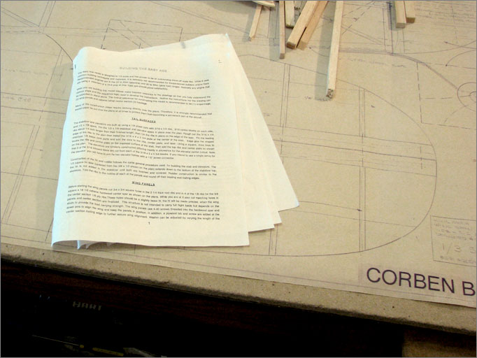
The instructions make a point of saying that you must have the plans AND the instruction “booklet” in order to build the model… many of the notes the builder will require are on the plans but some of the less obvious details will be noted in the booklet. … Yup! That’s what I am seeing.
I read the booklet several times over a period of weeks before I started building anything; looking at the plans, looking back at the written instructions and back at the plans until I could visualize the whole project. This is not a difficult build… just a lot OF it!
Here I go!
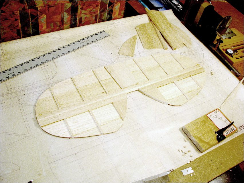
Per the order of operations in the booklet, I started the build with the tail feathers… the horizontal and vertical stabilizers, rudder and elevators. The construction of these parts is very straight forward and a good way to shake the rust off my brain and get me started into some serious woodworking!
Just looking at the parts…
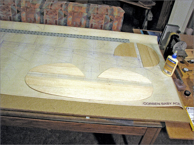
Assembling the pats into one place…
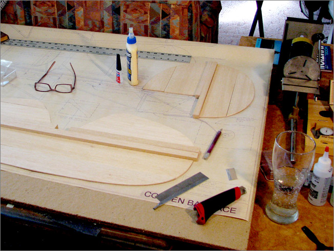
Here we go! … Gluing the first sticks to form the horizontal stabilizer!
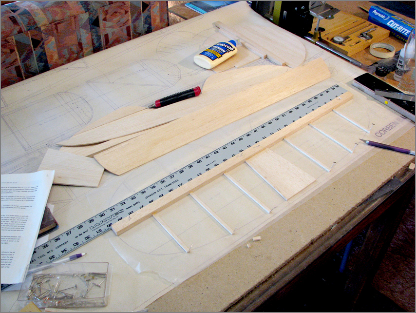
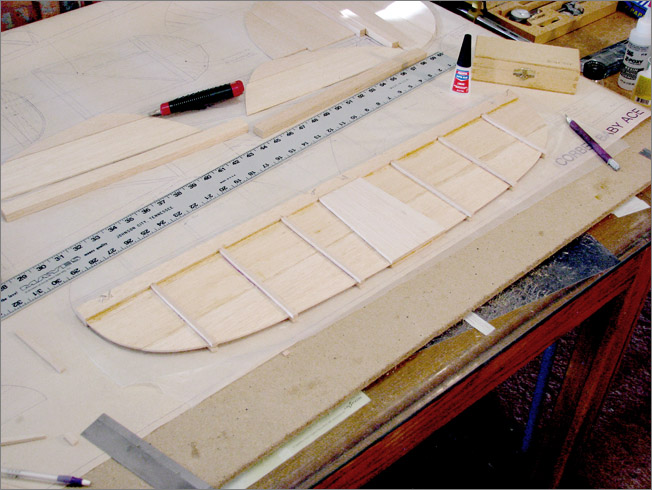
There we go… That’s one piece ready for a finish sanding!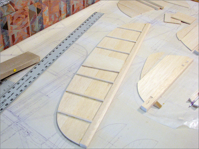
And so it goes… !
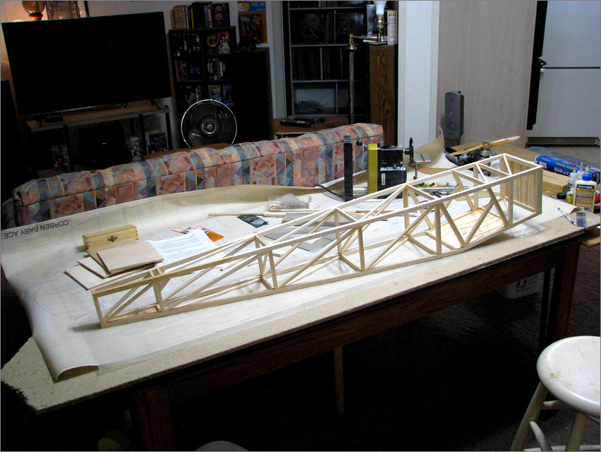
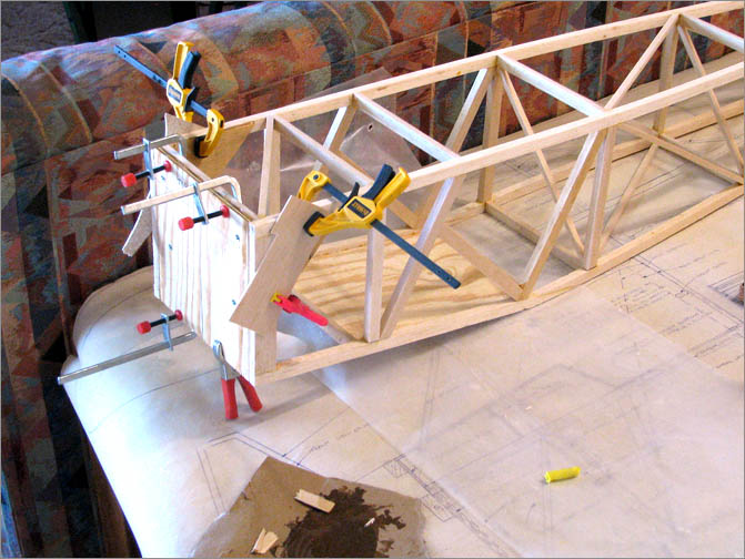
The Bridi 1/3 Corben Baby Ace Fuselage
I broke-away from the instruction booklet and skipped the wing and jumped right into the fuselage build… the wing can wait awhile!
STICKS… and more sticks!
The instructions suggested that I build the fuselage using an alphatic resin wood glue… the yellow woodworking kind. I used Titebond II Premium Wood Glue… I hope it works!
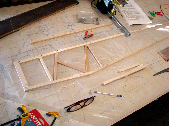
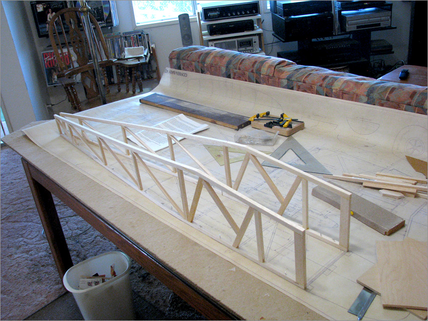
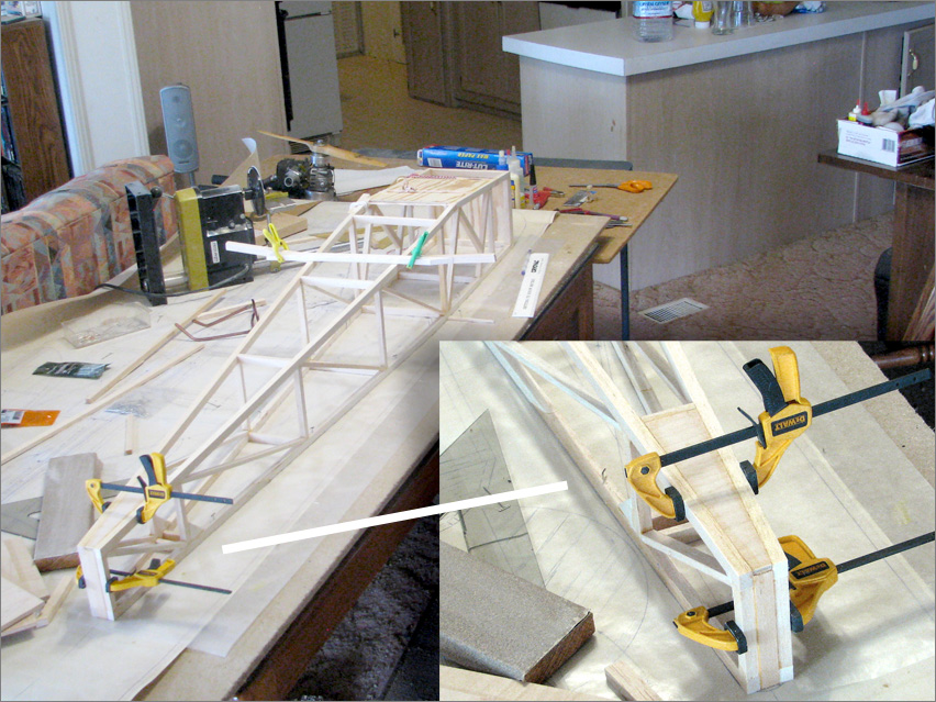
I followed the advice in the instructions and assembled the second side of the fuse directly on top of the first side so as to help assure that I build two identical sides…
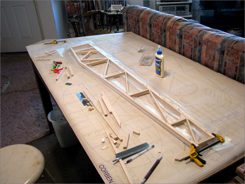
Two sides mounted upside down on the board…
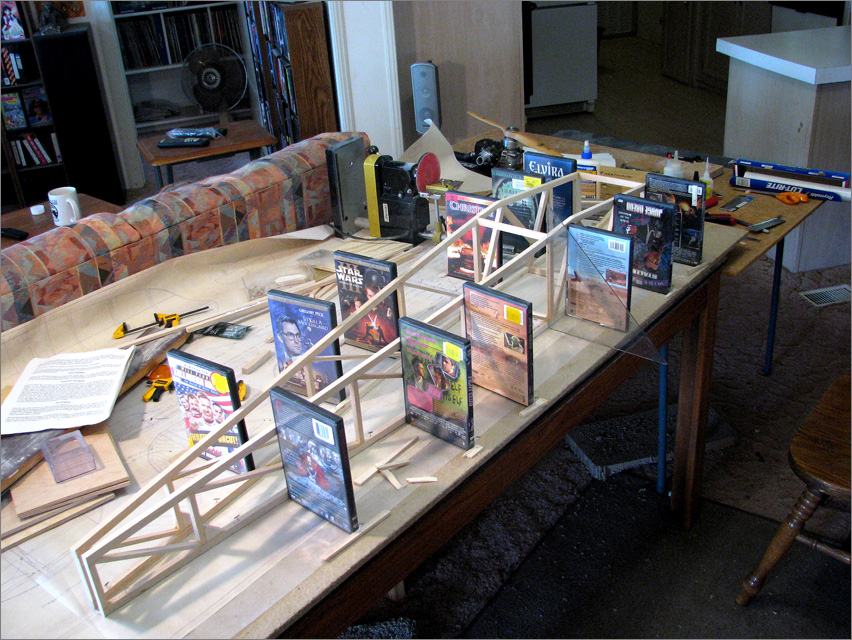
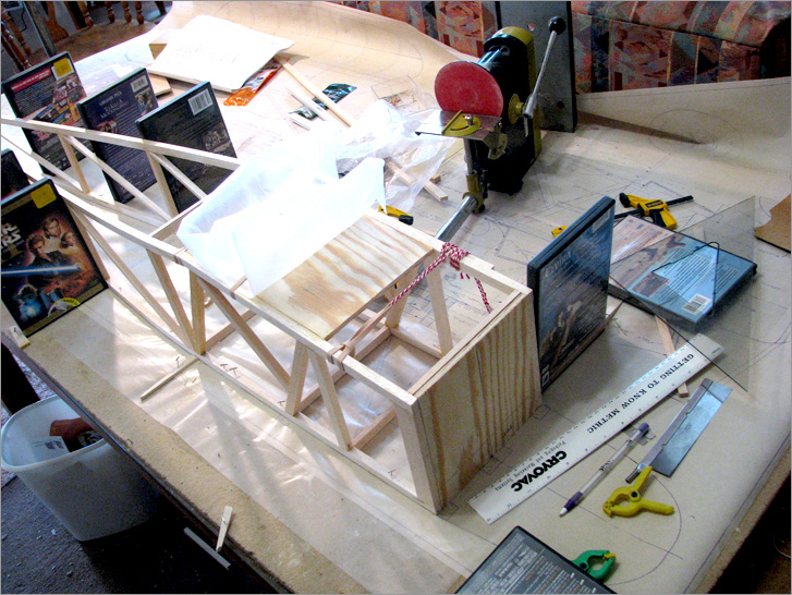
I did not have enough triangles to assure perfect vertical alignment for the whole length of both sides at once, so, I used DVD boxes as triangles!
I set the firewall in place on the model and used the landing gear mounting plate as a guide to firm-up alignment of the whole ship.
STICKS… and more sticks!
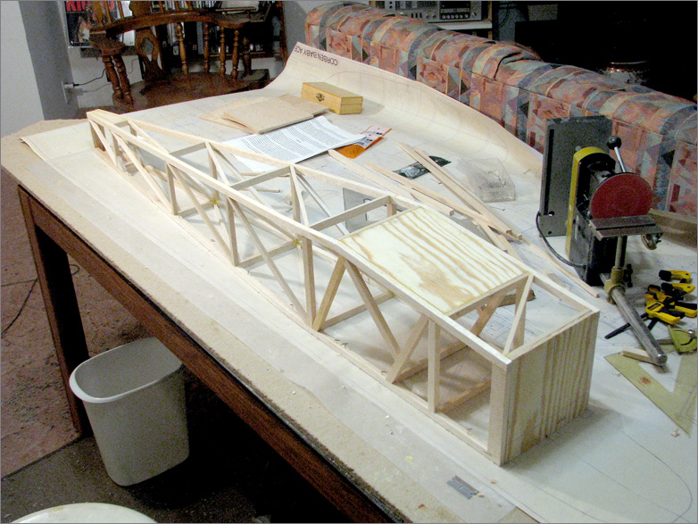
The instructions say “Install the firewall.”
But I gotta BUILD IT first!
Issues to be dealt with!
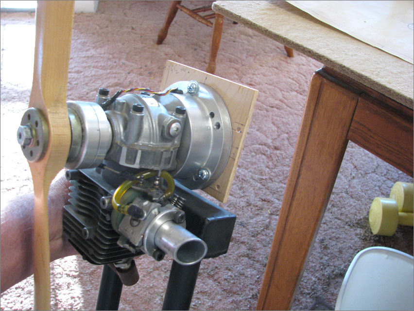
Working with the plans I can see that the motor needs to be extended away from the firewall so as to get the prop-mounting plate out to the end of the cowling. I will need to mount the engine inverted and raised up above the top of the actual firewall piece so as to be in line with the center-line indicated on the plans.
The engine will not simply “mount” to anything!… the exhaust manifold extends past the engine’s mounting plate area.

Here I am measuring the distance from the mounting plate to prop-mounting plate.

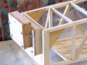
I began to formulate a plan. I would build two boxes out of 1/4″ plywood and attach them to the firewall.
I do some of my best thinking as I work with the PAINT program…
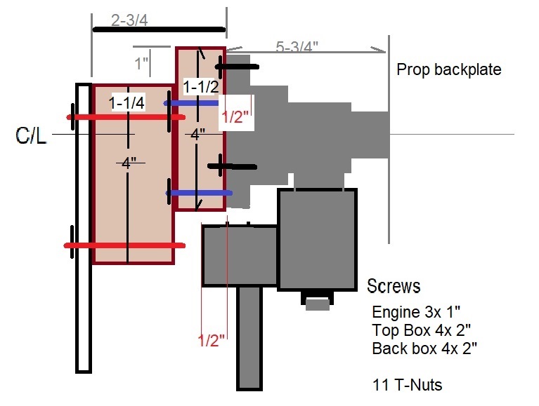
You can see that the motor-mount area needs to extend above the model’s firewall in order to get the engine’s centerline aligned with the model’s centerline. (The dimensions turned out to be not quite exact when I actually got into building the boxes.)
The front view of the assembly would look like this…
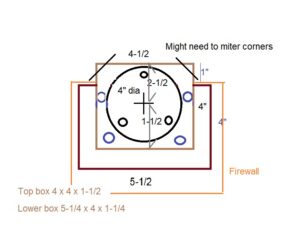
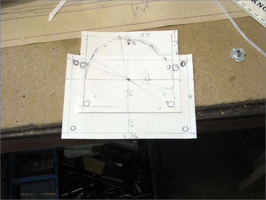
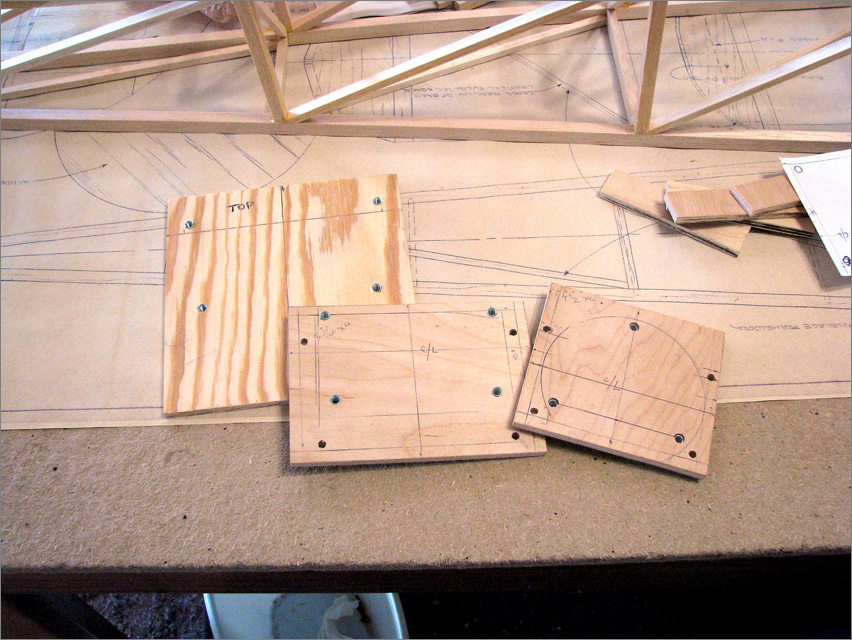
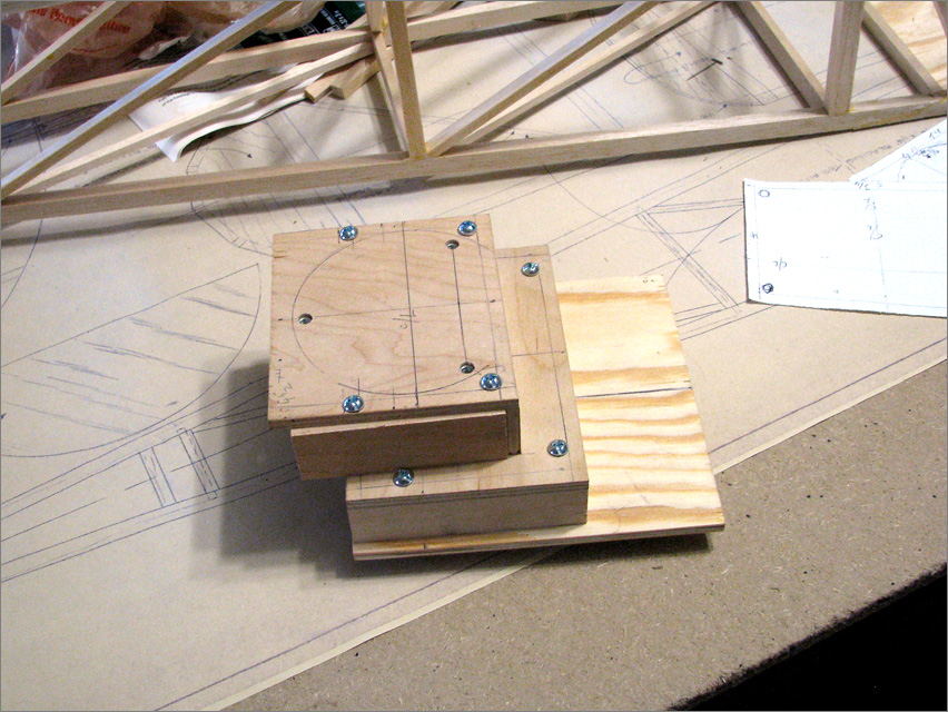
In the REAL world, I started with paper templates and cut the wood, drilled the holes… added T-Nuts and bolted the whole thing together with 10-32 screws! … Beefy! ( I hope!)
I spent a lot of time working on the paper templates. I believe they turned out to be almost exactly right.
As I moved to the actual wood, i had to be careful to allow clearances for all of the bolts, washers, and the wooden strips that would be the walls of the boxes.
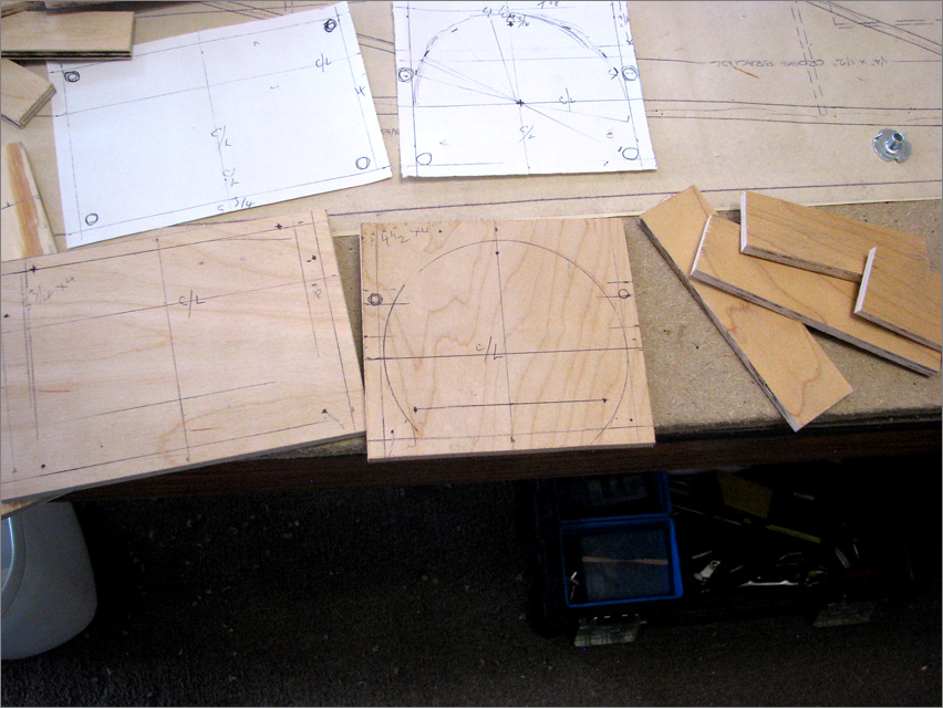
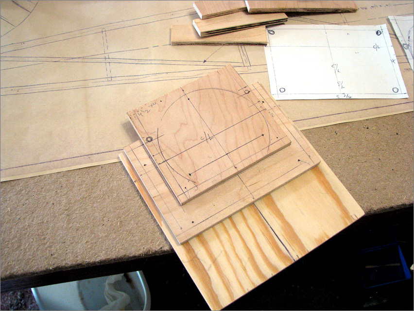
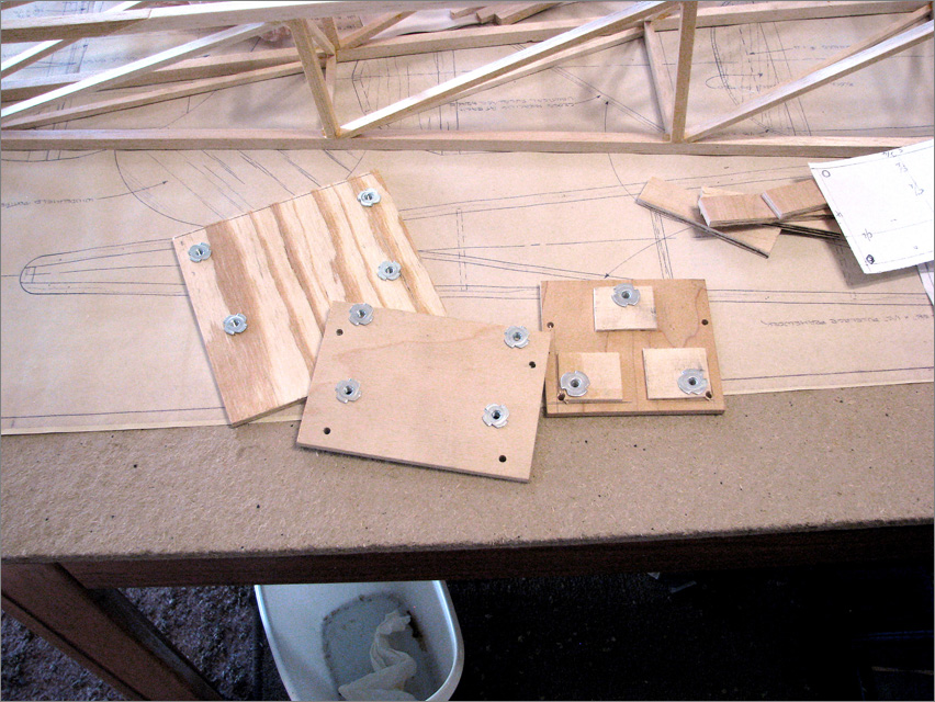
SEE BELOW that I will need to work-around a couple of places where the bolts and the plywood try to occupy the same exact space! … No real problem; this box idea is working well.
Today, 10/6/23… FIREWALL COMPLETION DAY
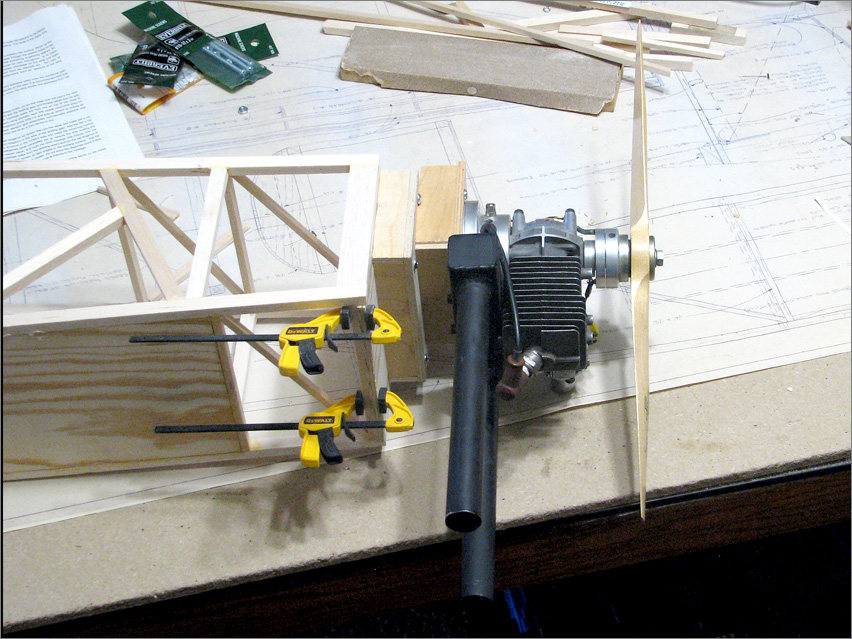
This morning, I popped out of bed early determined to install the firewall, finish the motor-mounting boxes, epoxy it all together and test-mount the engine. NOW it’s 5 PM and I have got all that done.
Here’s what I had at the end of the day:

I started the morning…
… by cutting large triangular gussets that would join the forward-most vertical posts to the firewall and to the upper longerons. I epoxied all of the pieces, there, in one swoop while using plenty of clamps to hold all in position. I used 30-Minute ZAP Z-Poxy and found that I did have enough working time to apply the epoxy, first, to each mating surface and then position and clamp the three parts, the firewall and the two gussets, against the verticals and horizontals which will hold the firewall in place.
I started with the ship in a vertical position so that gravity would hold the firewall while I clamped the large gussets into place. Then I was able to add clamps all around for a very secure glue job.

Then I was able to set the fuselage on the table and wait for the epoxy to set-up.

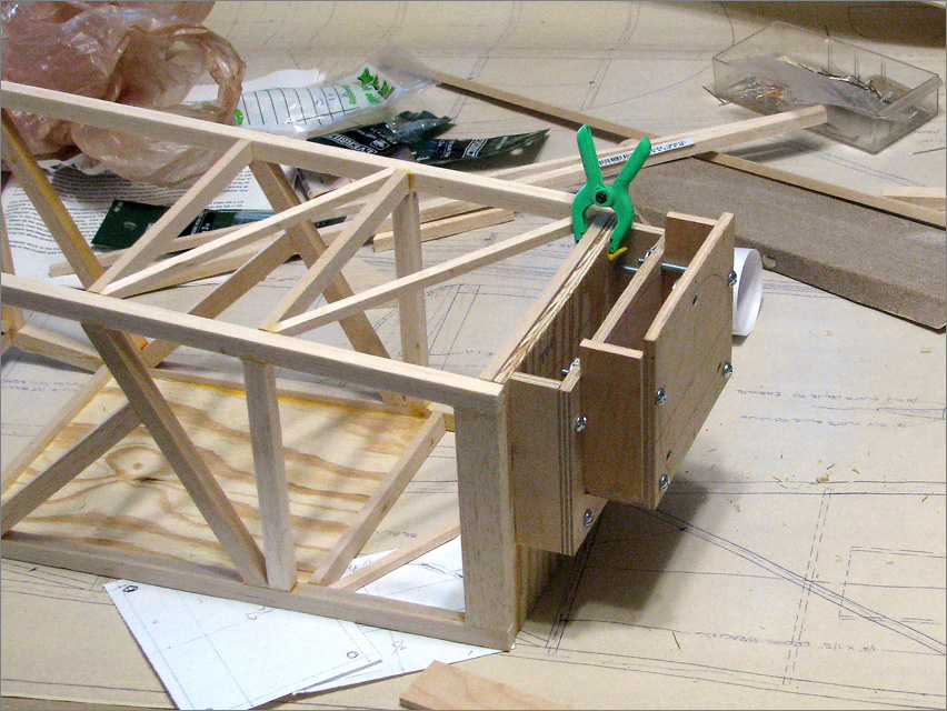
Next I assembled and epoxied the motor-mount boxes that I had created, previously.

The boxes are epoxied-together but not to eachother or to the firewall. Those large 10-32 screws actually mount the box to the firewall. Doing so lets me remove the boxes if I need to.
The actual motor-mount box had a design issue: screws needed to pass through the sidewalls! I used the table saw to deeply groove the sidewall panel to allow the screws to pass through. Then I used hardwood chunks to strengthen that grooved area. Lots of epoxy.

I noticed that the plans call for 2-degrees down-thrust. I accomplished that by carefully measuring and then reshaping the side walls to create that 2-degree down angle on the motor-mount.

I will be using thinned epoxy to fuel-proof all of the exposed plywood and balsa parts on the front end, there.
Now I can move on to Cabane Struts and Landing Gear!
That’s it for today… what a rush!